- Home
- Products
- Uncategorized
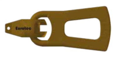
- Transport anchor High-quality steel


Attention! Object color from the photo may differ from real object because of your monitor screen color settings.
Transport anchor High-quality steel
Please note
- Transport anchor screws must only be used once
- Insert the screws without pilot-drilling
- Read the operating instructions in detail before use
- Users are to be trained before beginning use for the first time
- The transport anchor is to be examined for damage before each use and rejected if necessary
- The weight of the component to be lifted must not exceed the permissible value
- At least two attachment points per component to be lifted
The secure lifting system
Made of high-grade steel, this lifting attachment is used to lift all kinds of timber parts safely and easily. The transport anchors of the load group up to 1,3 tonnes are strictly to be used only in conjunction with the Ø 11 x 125 mm and Ø 11 x 160 mm Eurotec transport anchor screws. The Eurotec transport anchor screws must only be used once. They are to be screwed into solid wood (softwood), laminated veneer timber, glued laminated timber, cross laminated timber, stacked planks and laminated joists without pilot-drilling. Use in hardwoods is not permitted. The possible, or rather permissible, assembly positions can be found in our operating instructions, of which we will be delighted to provide you with a copy.
| Art. no | Dimensions [mm] a) | Load group | PU* |
| 110361 | 190 x 70 | Up to 1,3 tons | 1 |
a) Length x width
* Screws must be ordered separately (see below)
| Permissible lifting loada) per attachment pointb) | ||||
| γ c) | α d) | 11 x 125 mm | 11 x 160 mm | |
| Axial tension | 60° | 60° | 533 kg | 603 kg |
| 60° | 30° | 409 kg | 462 kg | |
| Diagonal tension | 60° | 90° | 462 kg | 522 kg |
| 60° | 0° | 139 kg | 157 kg | |
a) Calculation according to ETA-11/0024 with wood density ρk= 350 kg/m³; kmod= 0,9; γM= 1,3; yG= 1,35; g= 9,81 m/s²and dynamic factor ϕ2= 1,16.
All echanical values provided should be viewed as subject to the assumptions that have been made and represent example calculations. All values are calculated minimum values and are subject to typographical and printing errors.
b) At least two lines must be used per component to be lifted. Each line leads to exactly one attachment point. If more than two lines are attached, only two attachment points can be assumed to be load-bearing unless it is ensured that the load is distributed evenly
onto further lines (e. g. using a compensator) or that the uneven load distribution does not exceed the permissible loading of the individual lines.
c) γ – Inclination angle of line (chain, rope, lifting strap etc.); at least 60° according to BGR 500
d) α – Angle between grain direction and screwing axis
Please note: These are planning aids. Projects must only be calculated by authorised persons


